If your parts shift, chatter or bow under the clamps, the problem is probably the setup. Good CNC workholding locates the part on datums, then clamps it against cutting forces without distorting it.
For the wider picture of designing parts that are easy to hold and cut, read the cnc design guidelines.
| Item | Value |
|---|---|
| Degrees of freedom a rigid body has | 6 (3 translational, 3 rotational) |
| Contact points in 3-2-1 locating | 3 + 2 + 1 = 6 points |
| Example tight tolerance for workholding | ±0.01 mm |
| Suggested soft jaw material | 6061 aluminum |
| Soft jaw profile cut | 0.001-0.002 inch undersize |
| Suggested toggle clamp safety factor | 2x rated capacity |
These figures come from JLCCNC’s CNC workholding guide and the Machine Shop Tutorials work holding page. They are guidance values and can change, so check the sources before you rely on them.
What CNC workholding has to do
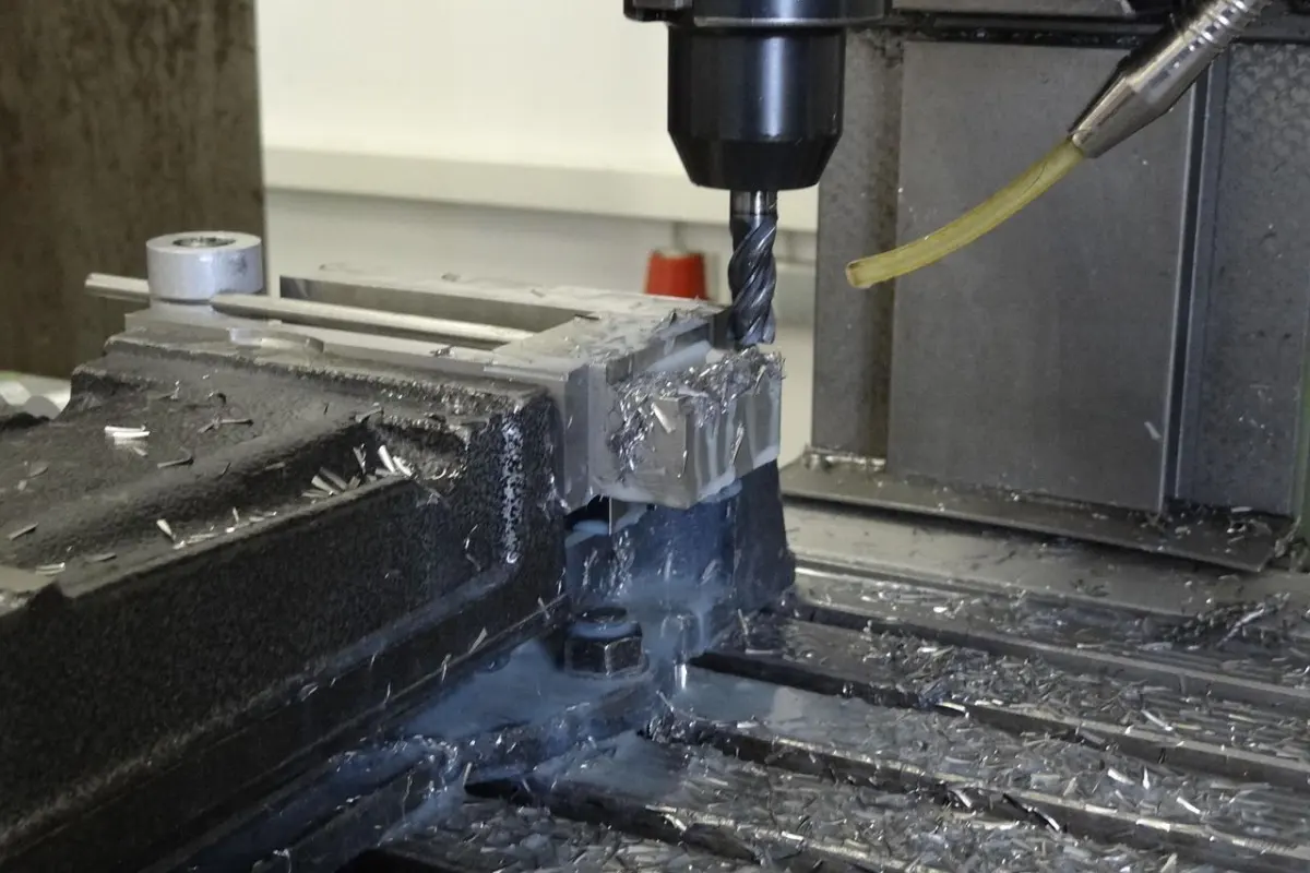
Workholding is the set of methods used to position and secure a part during machining. It affects dimensions, alignment and surface finish, because a stiff end mill cannot fix a part that bends under clamping pressure.
For tight tolerances such as ±0.01 mm, a stable setup matters as much as spindle accuracy, according to JLCCNC’s workholding guide. The same guide lists three jobs a good setup must do:
- Part positioning: set datums and lock degrees of freedom so the part cannot move unexpectedly.
- Force resistance: hold the part against cutting forces without lifting or sliding.
- Vibration suppression: reduce chatter and small movements.
Cutting forces push down into the table, sideways across it and upward against the clamps. The Machine Shop Tutorials page puts it plainly: your clamps need to fight all three, and gravity only helps with one.
Locating first: the 3-2-1 principle
Any rigid body has six degrees of freedom: three translational and three rotational. Locating defines where the part sits in space, and clamping keeps it there against cutting forces without over-constraining or deforming it.
The 3-2-1 principle is the common way to control all six movements:
- Three points establish the primary datum plane. They stop movement along Z and rotation about X and Y.
- Two points define the secondary plane. They stop movement in one horizontal direction and rotation about Z.
- One point locks the final degree of freedom.
In a pin-based fixture, MISUMI’s locating basics post describes three pins forming the bottom datum in the z axis, two in the x axis and one in the y axis. It also calls locating pins the most common locating method and one of the most crucial components in fixture design.
Together, those six contact points fully constrain the part without over-constraint. Over-constraining can introduce internal stress, distortion or instability during cutting, while incomplete locating lets even small cutting forces cause micro-movement that shows up in tolerance and surface finish.
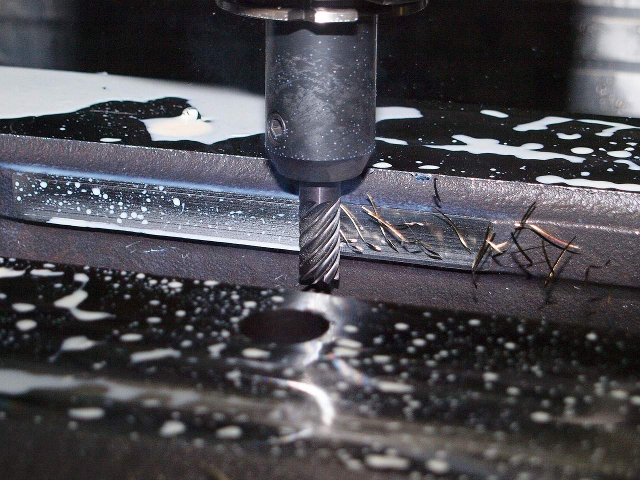
How do you clamp without distorting the part?
Clamping is where good locating is most often undone. Even pressure is the goal, and the tutorial’s rule of thumb is that multiple light clamps always beat one heavy one.
Good clamping, as the tutorial describes it:
- Close to the cut, so you support the part where the forces happen.
- On solid sections rather than thin walls.
- Low on the part, which means less leverage for lifting.
- Spread over a wide area, as the JLCCNC guide advises for thin or flexible parts.
When a part was straight until you clamped it, the tutorial points to a short list of causes: over-clamping, uneven support, heat buildup, residual stress and clamps that are too small. Jack screws that support the middle of long parts are one fix for bowing.
A quick seating check helps too. After clamping, tap each parallel: they should ring the same, and a dead one means the part is bent or not seated.
Common workholding methods and their limits
No single method fits every job. The table below summarises what the sources say about each option.
| Method | Good for | Watch out for |
|---|---|---|
| Vise with parallels | General work; parallels lift the part for tool clearance and spread clamping force | Dirty or non-parallel jaws; check seating with the tap test |
| Soft jaws | Round parts, finished surfaces, odd shapes, production runs, thin walls | Each set is tied to one job |
| Fixture plate | Repeat work with tapped holes for clamps and dowel pins for location | You have to design and build it |
| Toggle clamps | Quick loading and repeatable pressure | Do not trust the ratings alone |
| Vacuum fixture | Thin, flat parts with no clamp marks | Limited cutting force; needs good seals |
| Magnetic chuck | Fast setup with no clamp interference | Ferrous materials only; limited holding power; chips stick |
The method notes in this comparison follow the JLCCNC guide, with fixture detail from the Machine Shop Tutorials.
Soft jaws deserve a closer look. The tutorial starts them in 6061 aluminum, machines them in place for accuracy and cuts the profile 0.001-0.002 inch undersize.
For toggle clamps, the tutorial recommends a 2x safety factor instead of trusting the rating. For magnetic chucks, it says never to trust magnets alone for heavy cuts and to use backup clamps for roughing.
Matching the method to the cut
Workholding must never block the tool. Clamps, vises and fixture pins must not interfere with end mills, drills or probes, and short overhangs reduce deflection.
Tool diameter and reach decide how much room your clamps can take, so plan the fixture alongside end mill selection. Because clamps and locators must resist the main cutting forces, the cutting parameters in speeds and feeds also shape how much holding a roughing pass needs.
A simple order of work keeps decisions clear:
- Choose the datums and locate the part so all six degrees of freedom are controlled.
- Place clamps to resist the main cutting forces, close to the cut and low on the part.
- Check that no clamp, pin or vise path crosses the tool path.
- For thin or flexible parts, spread the load and add supports or soft jaws.
- Confirm the part is seated before cutting.
Frequently asked questions
What is the 3-2-1 rule in CNC workholding?
Show answer
It is a locating method using three points for the primary datum plane, two for the secondary plane and one for the last degree of freedom. Between them they remove all six degrees of freedom without adding redundant contacts.
Can you rely on a magnetic chuck for heavy cuts?
Show answer
No. The Machine Shop Tutorials page says never to trust magnets alone for heavy cuts and to use backup clamps for roughing. Magnetic holding also works on ferrous materials only.
Why does a part bend after clamping?
Show answer
Common causes are over-clamping, uneven support, heat buildup, residual stress and point loading from small clamps. Spreading the force over a wide area and supporting the part usually helps.
How much safety margin should toggle clamps have?
Show answer
The tutorial suggests using a 2x safety factor rather than trusting the stated ratings. Check the figure against your own clamp data before you rely on it.