Not sure what numbers to type into the control? Your speeds and feeds start from the material’s surface speed and the tool’s chip load, then get limited by your machine. Treat the result as a starting point.
This page is part of the cnc design guidelines for precision machining.
| Item | Value |
|---|---|
| Standard tools with tested cut data in one public calculator | 214,000+ |
| Machining data behind that calculator | 67 years, since 1959 |
| Adjustable power safety headroom | 40-95% |
| Example depth-of-cut limit (titanium slot, rigid setup) | 0.5″ |
The figures come from the RobbJack speeds and feeds calculator page, a third-party tool used here as a neutral example. Settings and data can change, so check the source before you rely on them.
What speeds and feeds actually set
Speed is how fast the cutting edge travels through the material, and feed is how fast the tool advances. The calculator page describes surface speed as the cutting speed at the edge, set by the material, as described on the RobbJack page.
Feed rate follows from the spindle speed and the chip load, which is the feed per tooth. Chip load is judged against a tested limit for the tool, so the same number can be gentle on one cutter and aggressive on another.
A full set of results usually covers these values:
- Spindle speed in RPM
- Surface speed in SFM or metres per minute
- Chip load per tooth
- Feed rate in inches or millimetres per minute
- Width of cut and depth of cut per pass
- Metal removal rate and spindle power
The inputs that change your numbers
Material and grade are the starting point. Once you pick them, the calculator loads a tested surface-speed and chip-load band, plus a recommended coating.
The remaining inputs describe the cut and the setup:
- Cutter end: square or radius, or ball.
- Cutting diameter.
- Operation: slot or profile.
- Strategy: conventional or trochoidal.
- Setup rigidity: rigid, or light and weak.
- Total depth of cut.
- Your machine’s maximum spindle RPM, feed rate and power.
The tool geometry then turns surface speed and chip load into spindle RPM and table feed. The result is a roughing card and a finishing card, as the source page explains.
Slotting, profiling and trochoidal cuts
Slotting is a full-width cut, so the edge is engaged the whole time. That makes it the most demanding operation, while profiling takes less width and can run faster.
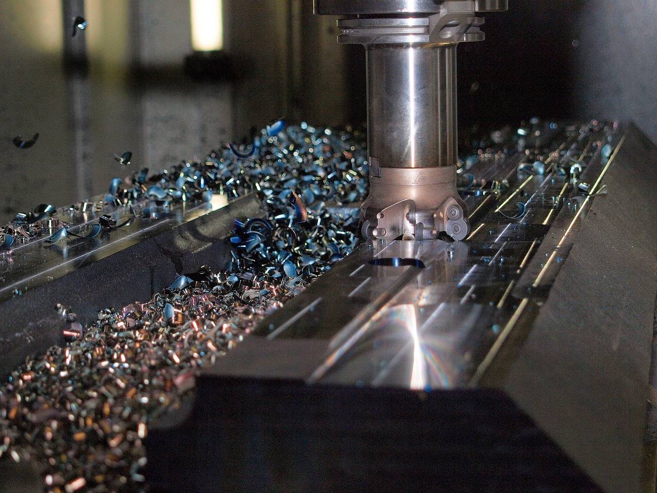
Trochoidal milling changes the picture. A light radial width keeps the edge in the cut for only a fraction of the time, so the allowable chip load rises and the tool can take a full-depth pass, according to the RobbJack page.
Why rigidity and workholding matter
The source calls rigidity the most overlooked factor in tool life. Thin walls, long reach or anything that can vibrate should be set to light and weak, which backs off feed and chip load to keep the cut stable.
Your fixture is part of that answer, so read up on cnc workholding before you choose a rigid setting. A rigid setup unlocks the faster numbers, but only if the part really is held that firmly.
Keeping the cut inside your machine’s limits
A good calculation respects the spindle. In the RobbJack tool you enter maximum RPM, feed rate and horsepower, plus a power safety headroom between 40-95%, as described on the source page.
If a cut would exceed that headroom, the tool reduces the depth automatically and flags it. You enter the full depth you need, and it divides that into passes that stay inside both the tool geometry and your machine’s power.
For hardened die and mold grades, it splits the advice into separate wall and floor passes. The example setup shown on the page, a titanium slot in a rigid setup, shows a depth-of-cut limit of 0.5″.
Proving the numbers before production
The source says its recommendations are computed starting points based on typical conditions, not guarantees of performance, tool life or fitness for your application. You remain responsible for checking every parameter against your machine, spindle, toolholding, workholding and guarding limits, per the RobbJack page.
Prove the parameters on a test cut before production. Then measure the part against the drawing, and gd&t basics explains how the tolerance callouts you check against are read.
Frequently asked questions
Are calculator speeds and feeds guaranteed?
Show answer
No. The RobbJack page describes its results as computed starting points based on typical conditions, not guarantees of performance, tool life or fitness for your application.
Can I run faster than the recommendation?
Show answer
Possibly. The source describes its numbers as deliberately conservative and says many shops run faster once the process is dialed in. Prove any increase on a test cut first.
Why is slotting harder than profiling?
Show answer
The source ranks slotting as the most demanding operation because it uses the full cutter width. Profiling uses less radial width, so its recommended feeds can be higher.
What does the trochoidal strategy change?
Show answer
It uses a light radial width, so the edge spends only a fraction of the time in the cut. The calculator then raises the allowable chip load and drives a full-depth pass.
Which rigidity setting should I pick for a thin wall?
Show answer
Choose light and weak. The source says that setting suits thin walls, long reach and anything that can vibrate, and it backs off feed and chip load to keep the cut stable.