If you want to know what happens between a digital drawing and a finished part, the cnc machining process runs from CAD model to CAM toolpath, G-code, setup, cutting and inspection. Each stage is covered in order.
This page is part of a wider look at precision cnc machining, from design through inspection.
| Item | Value |
|---|---|
| Steps in the CIMCO CAD-to-part workflow | 9 steps |
| Positional accuracy of modern CNC machines | ±0.005 mm to ±0.025 mm |
| Numerical control systems first developed | Mid-1950s |
| Tolerance on critical mounting features in a bracket example | ±0.05 mm |
| Surface roughness on that bracket’s mounting face | Ra 1.6 μm |
These figures come from the CIMCO CNC Book and a FirstMold guide. They can change, so check the source before you rely on them.
The CNC machining process at a glance
CNC stands for computer numerical control. It is a subtractive process: as The Manufacturer’s beginner guide puts it, computer-controlled machines remove material from a workpiece to create a desired shape.
The CIMCO CNC Book breaks the route from drawing to part into 9 steps:
- Begin with a CAD model.
- Establish job parameters, including the CNC coordinate system and the stock shape and size.
- Select the CNC process.
- Select the cutting tool and machining parameters.
- Select the driving CAD geometry.
- Verify the toolpath.
- Post process.
- Transfer the G-code program to the CNC machine.
- Set up and operate the machine to make the part.
Other guides group the same work differently. The Manufacturer’s breakdown runs to 7 steps, from material selection and preparation to final assembly or delivery, so the exact count is a way of teaching the job rather than a fixed rule.
Design and programming: CAD, CAM and G-code
Everything starts with a digital model. According to one CNC setup guide, CAD defines the part geometry, while CAM turns selected geometry into tool motion.
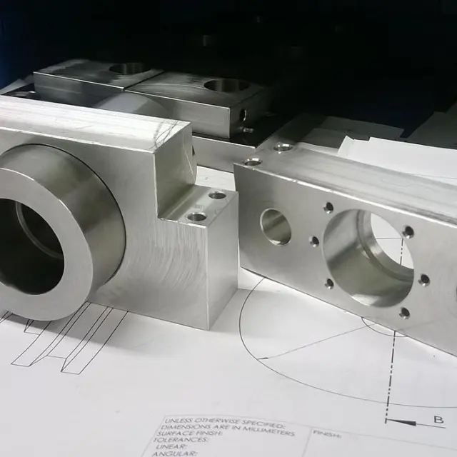
Design choices decide whether a part can be cut at all. In a FirstMold example, a bracket measuring 120 mm × 80 mm × 10 mm, engineers added fillets (R3 mm on the internal corners) because standard end mills cannot machine sharp internal corners. They also kept enough wall thickness around the pocket to prevent deformation during machining.
The same model carries the requirements. That bracket specifies a tolerance of ±0.05 mm on critical mounting features and a surface roughness of Ra 1.6 μm on the mounting face, as the FirstMold guide describes.
Next, CAM software converts the design into a toolpath, a set of coordinates that define the movement of the cutting tool, according to The Manufacturer. G-code is the language that carries those movements to the machine, along with spindle speeds and cutting depths.
A typical line reads G01 X50 Y25 Z-5 F200. It instructs the machine to move to coordinates (50,25,-5) at a feed rate of 200 units per minute, as The Manufacturer’s guide explains.
The CIMCO workflow adds checks before anything is cut: verify the toolpath, post process, then transfer the program. The same chain serves prototypes and repeat orders alike, since The Manufacturer notes that CNC machining suits both prototyping and mass production, so you can apply it to cnc prototyping as readily as to larger runs.
Setting up the machine and running a dry run
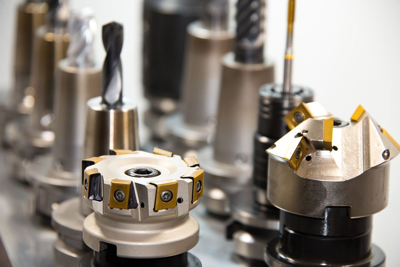
Material comes first. The Manufacturer lists metals such as aluminum, steel and titanium and plastics such as ABS, nylon and PEEK, cut into an appropriately sized blank and secured with clamps or vises.
The operator then installs the cutting tool and sets tool offsets, which are reference positions. Spindle speed, feed rate and depth of cut are entered as machining parameters.
A few machine parts matter most during a job:
- Spindle: the rotating component that holds the cutting tool.
- Worktable and fixtures: they hold the material and secure it in place.
- Motors and drive system: they control movement along multiple axes (X, Y, and Z).
- Coolant system: it prevents overheating, reduces tool wear and improves surface finish.
- Control panel: operators use it to input commands, adjust settings and monitor operations.
Machines with more axes than the basic X, Y and Z are covered in the guide to 5 axis cnc machining.
Before real cutting, the program is loaded into the controller and the operator performs a dry run. This verifies tool movements without cutting and helps detect any potential errors.
Cutting, inspection and finishing
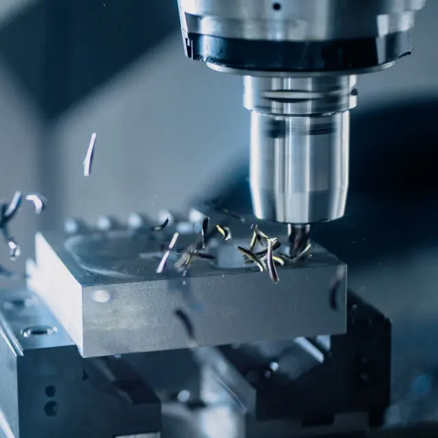
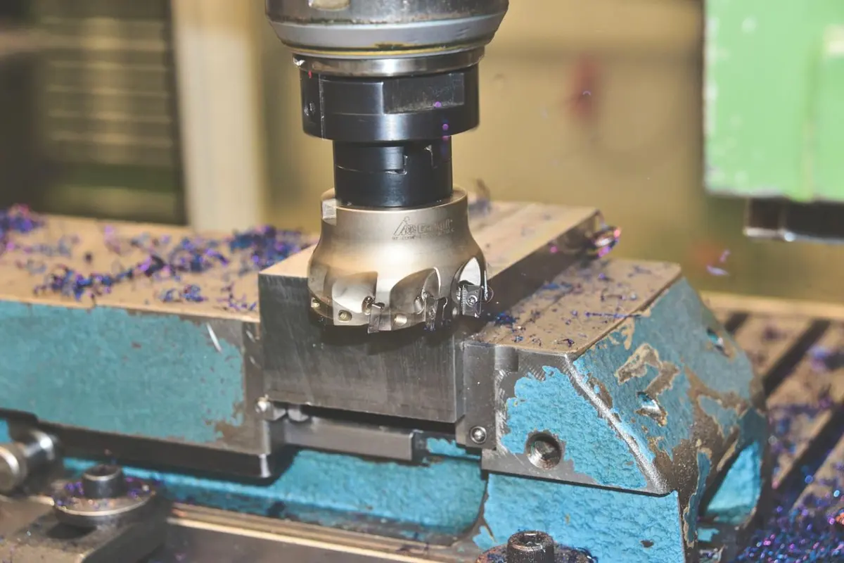
Once everything is set, the machine executes the programmed instructions. The cutting tool removes material layer by layer to shape the part, using operations such as:
- Milling, which cuts away material using rotating tools.
- Turning, which shapes cylindrical parts on a lathe.
- Drilling, which creates holes in the workpiece.
Afterwards the part is inspected against its specification. Calipers, micrometers and coordinate measuring machines (CMM) are used to check dimensions and tolerances, according to The Manufacturer.
Depending on the application, finishing may follow: deburring, polishing, anodising or painting. If the part belongs to a larger assembly it goes on to further processing, and otherwise it is packaged and shipped.
How precise can a CNC machined part be?
FirstMold states that the positional accuracy of modern CNC machines can reach ±0.005 mm to ±0.025 mm, quantified using calibration protocols like the ISO 230-2 standard, as its CNC machining guide explains.
That is a machine capability, not a promise for every part. The same guide says high precision is determined by the design of the machine, the accuracy of the calibration, the environment and the process needs, and its bracket example asks for ±0.05 mm, a different measure from positional accuracy.
The idea is old. The guide traces CNC machining back to the mid-1950s, when numerical control systems were based on punched tape, whereas today’s systems rely on software and real-time machine control.
Frequently asked questions
What is the first step in the CNC machining process?
Show answer
In the CIMCO CNC Book’s workflow, you begin with a CAD model. Job parameters such as the coordinate system and stock size come next.
What does G-code do?
Show answer
G-code is the language used to communicate with CNC machines. Its commands dictate tool movements, spindle speeds and cutting depths.
Can a CAD drawing go straight to the machine?
Show answer
Not in the workflow CIMCO describes. The CAD model is the starting point, and toolpath selection, verification and post processing come before the G-code program is transferred to the machine.
Why run a dry run first?
Show answer
A dry run, done without cutting, verifies tool movements and helps detect potential errors before material is removed.
How is a finished part checked?
Show answer
Tools like calipers, micrometers and coordinate measuring machines (CMM) are used to check dimensions and tolerances against the specification.