Your part just came off the printer and it isn’t ready to use. Post processing 3d printed parts means removing supports, relieving stress, machining critical features and finishing surfaces, and which steps you need depends on the job.
This page sits within the wider topic of 3d printing for manufacturing, where post-processing is one stage of a longer workflow.
| Item | Value |
|---|---|
| Share of metal AM printing cost taken by post-processing | Approximately 27% |
| As-printed DMLS tolerance | ±0.003 in. (0.076 mm) plus ±0.001 in. for each additional inch |
| DMLS tolerance after post-process CNC machining | As tight as ±0.001 in. |
| Metal post-processing step groups | 3 (process-inherent, mechanical, visual) |
The cost share comes from Aniwaa’s metal AM post-processing guide (updated October 2022), and the tolerances from Protolabs’ metal 3D printing design tip. Figures can change, so check the source before you rely on them.
What post processing 3d printed parts involves
According to Additive-X’s post-processing guide, post-processing covers everything that happens to a part after the printer stops and before it is ready for use. Depending on the process and material, that can include:
- Support removal
- Washing and UV curing (for resin prints)
- Sanding and surface finishing
- Vapour smoothing
- Heat treatment or annealing
- Painting or coating
- Assembly of multi-part prints
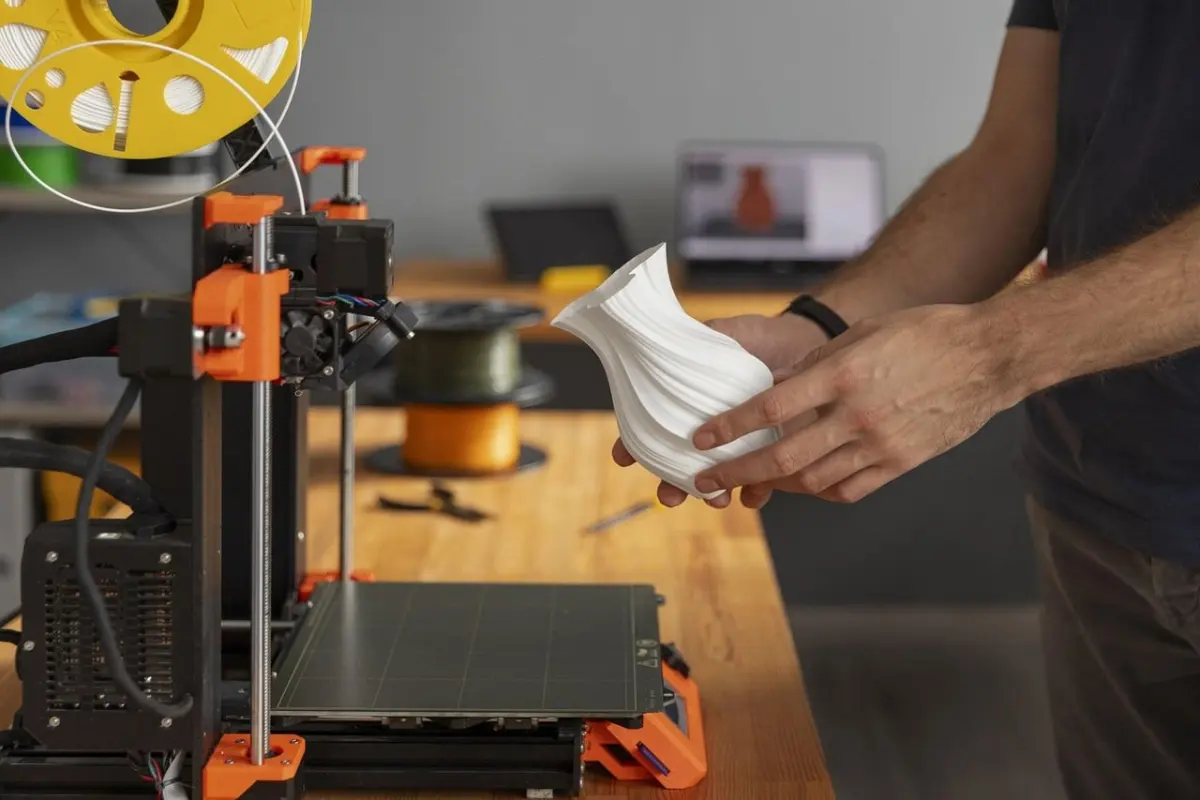
Not every part needs every step. The same guide notes that a quick prototype for a fit check might need nothing more than support removal.
Most of the detail in the sources for this page covers metal printing, so the sections below lean that way. Aniwaa divides metal steps into three groups by their intended effect:
- Process-inherent: depowdering, support removal and stress relief.
- Mechanical: heat treatments that improve hardness, ductility and fatigue life, plus work toward tighter tolerances.
- Visual: smoothing, polishing and coloring to reduce roughness and remove blemishes.
Depowdering, support removal and stress relief
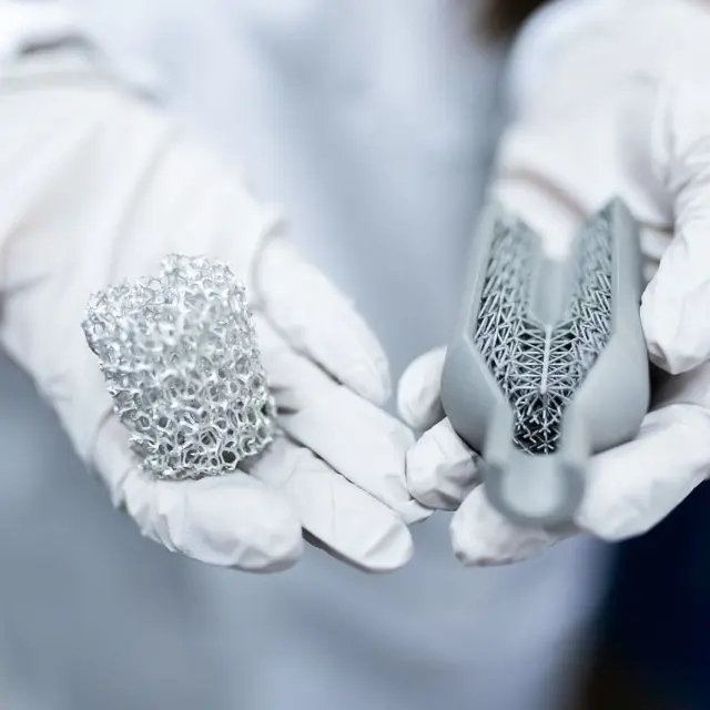
For powder bed processes, depowdering comes first. Unionfab’s guide describes it as removing loose powder trapped inside internal cavities, channels, lattice structures and other difficult-to-access areas.
Next comes stress relief, which is usually done before the part leaves the build plate. Unionfab says this reduces residual thermal stresses and the risk of distortion, and Aniwaa likewise describes it as performed while the piece is still attached to its supports.
After that, the part has to be separated. Protolabs says parts are typically removed from the build plate using wire EDM or a band saw, and support material is then removed with hand tools. Aniwaa adds that harder materials such as Inconel may call for CNC machining, robotic arms or wire EDM instead.
Heat treatment then tunes the material. Aniwaa describes hot isostatic pressing (HIP) as combining high heat with pressure to increase part solidity and density, deal with residual stress and greatly enhance fatigue life. Annealing, a controlled heating and cooling cycle, is the other common option, aimed at stress relief and better ductility.
When does machining a printed part make sense?
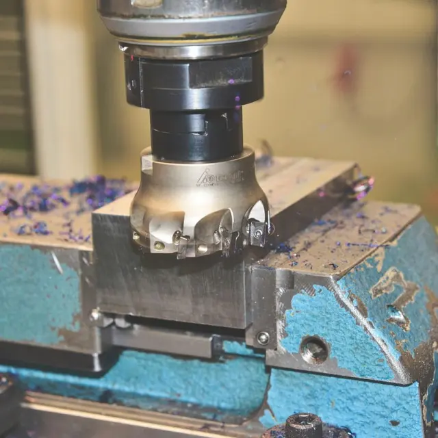
Printing gives you freedom of shape, but not always the accuracy of a cut surface. Protolabs states that its DMLS process can produce parts to ±0.003 in. (0.076 mm) plus ±0.001 in. for each additional inch, while post-process CNC machining can reach tolerances as tight as ±0.001 in.
That is why machining is usually reserved for the few features that matter, such as mating faces, bores and threads. The rest of the part can keep its printed geometry. This pairing of printing and cutting is covered further in the guide to hybrid manufacturing additive and subtractive.
Unionfab lists the secondary operations most often applied to printed metal parts:
- CNC milling for flat mounting surfaces, mating faces and datum surfaces.
- CNC turning for cylindrical features, shafts and rotational components.
- Drilling and reaming to bring printed holes to precise diameters and fits.
- Tapping and thread milling for internal threads where printed threads fall short.
- Precision grinding for sealing faces, bearing journals and tight fits.
Plan for this at the design stage. Unionfab’s tip is to give critical surfaces sufficient machining allowance and accessible reference datums. If an awkward printed shape is hard to hold while cutting, the page on 3d printed jigs and fixtures looks at printed workholding.
Surface finishing options for printed parts
Unionfab notes that as-printed metal surfaces often retain partially fused particles and visible layer-related texture. Sam Materials adds that pores, lack-of-fusion zones and micro-cracks near the surface can become stress concentration points and significantly reduce fatigue life. Finishing is therefore about performance as well as looks.
Common methods named in the sources include:
- Abrasive blasting removes loose particles and gives a more uniform matte or satin finish.
- Vibratory finishing deburrs edges and gives a more consistent finish across batches.
- Electropolishing removes microscopic surface peaks to improve smoothness and cleanability.
- Abrasive flow machining polishes complex internal channels.
- Shot peening forms compressive stress on the surface, which increases fatigue strength.
- Plating and coatings modify hardness, wear or corrosion resistance.
Sam Materials gives two numbers worth knowing. Abrasive flow processing of rocket engine cooling channels can reduce inner roughness from Ra 12 μm to Ra 0.8 μm, and electrochemical polishing typically removes a layer between 0.0001 and 0.0025 inches thick. Material removal of that size matters if a surface is already near its tolerance limit.
How should you plan the steps and the cost?
Post-processing is rarely a small line item. Aniwaa cites a Wohler’s Report figure putting it at a sizeable share of metal AM printing costs, and a market report describes it as often more expensive and time consuming than the printing itself.
A short planning routine keeps that cost under control:
- List the features that carry a tolerance, a fit or a seal, and mark them for machining.
- Leave machining allowance and reachable datums on those surfaces.
- Check how powder and supports will leave any internal channel.
- Pick each finish for its function, such as fatigue, corrosion or appearance, rather than for habit.
- Leave out every step the part does not need, as a fit-check prototype shows.
Frequently asked questions
Does every 3D printed part need post-processing?
Show answer
No. Simple models made only to test fit can often skip everything except clearing supports, as Additive-X’s guide describes. Parts for demanding use usually need more.
Why machine a 3D printed part at all?
Show answer
Machining tightens critical features. Protolabs states that post-process CNC machining can reach tolerances as tight as ±0.001 in. on DMLS parts, against ±0.003 in. plus ±0.001 in. per additional inch as printed.
When is stress relief done on metal parts?
Show answer
Typically before the part is removed from the build plate, according to Unionfab. The aim is to reduce residual thermal stresses and the risk of distortion.
How much of the cost is post-processing?
Show answer
For metal AM, Aniwaa cites a Wohler’s Report figure of approximately 27% of printing costs, in a guide updated October 2022. Your own share will vary with the process, material and finish.